
The problem.
I needed a wireless device that would allow me to take advantage of all the ‘free’ wi-fi hotspots around but at the same time be a little under the radar, with no GPS that could be used by apps or websites to report back my physical location, no mobile connectivity that could be used to track me from cell to cell, no microphones that could be used to record any conversations I might be having, no cameras that could be used to take a photo of me or my location, whilst being innocuous enough to not raise suspicion if I am using it.
Enter the Samsung S3 Mini GT-I819N project.
Why an S3 Mini? I needed something modular and was looking at several of the Samsung S range as iFixit has several excellent how-to guides that show these have the modularity I was looking for. However, I inherited an S3 Mini from a friend, so this is a zero-cost project, which is nice.
To access the internals of the phone, whip the back cover off and remove the battery, then using a 1.5mm cross point screwdriver undo the 10 machine screws circled in Figure 1.
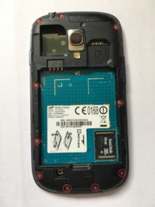
Figure 1.
Gently pry off the plastic frame so you have full access to the main PCB, as in Figure 2. (My photos show AFTER the cameras and aerials have been removed so don’t be surprised that yours looks a little different)
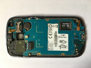
Figure 2.
Now using tweezers gently pop off the two push connectors circled in Figure 3.
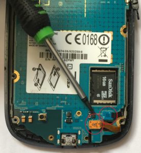
Figure 3.
Now you can gently lift the main PCB up from the right-hand side, as you look at it from the back, hinging on the left. As you lift you will see the push fit connector circled in Figure 4, again using tweezers gently pop this off, now you have separated the main PCB from the phone, and its time to start removing things permanently.
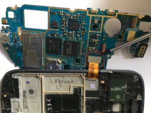
Figure 4.
The front and rear cameras are held in place using old fashioned style ribbon cable connectors, you just gently lift the beige cam locks circled in Figure 5 and the ribbon cable slides out.
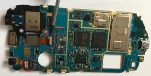
Figure 5.
To remove the GPS antenna, undo the screw circled in Figure 5 and then turn over the PCB to access and pop off the push fit connector circled in Figure 6.
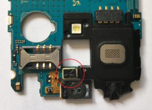
Figure 6.
The whole black unit now will separate from the main PCB. The last easy bit is the main microphone, circled in Figure 7, this is a surface mount component and requires the application of a bit of hot air from above and then it can be tweezered off.
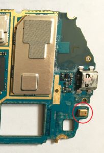
Figure 7.
In classic Haynes manual style, assembly is simply the reverse of disassembly, not forgetting to leave a few bits out. Now I understand there is an additional noise cancelling microphone fitted, and when I locate it, if it easy to remove I will update this. Also, I know that though I will not install a SIM card in this unit it can be tracked by its IMEI code, if I use the unit for emergency calls. It does not register with a network until an emergency call is initiated but I understand that other than that it is not visible. And anyway lets not fool ourselves, I have just posted this on the internet, its not like I am a master criminal wanting to get off the grid, I just don’t want any applications I install later as part of this project reporting back on me to their developers, but more on that later.